
One of the first modifications I made to my Hottop was to install a temperature probe in the bean chute cover. That method works great and is quick and simple but over time it becomes a nuisance to deal with the probe when loading beans and moving the roaster. A more permanent and clean installation is therefore necessary. Below is how I installed two new probes through the back wall of my HotTop KN8828-P2 (other models may require modifications to the process below). Full instructions are below the photos.
See also: HotTop Resources

I combined methods discussed and documented by others in this forum and this one, both on Home-barista.com and also this forum at S1Cafe.com. There is a great discussion about thermometry here.
- 2 probes XCIB-K-1-4-3 (K-type, grounded welded junction,
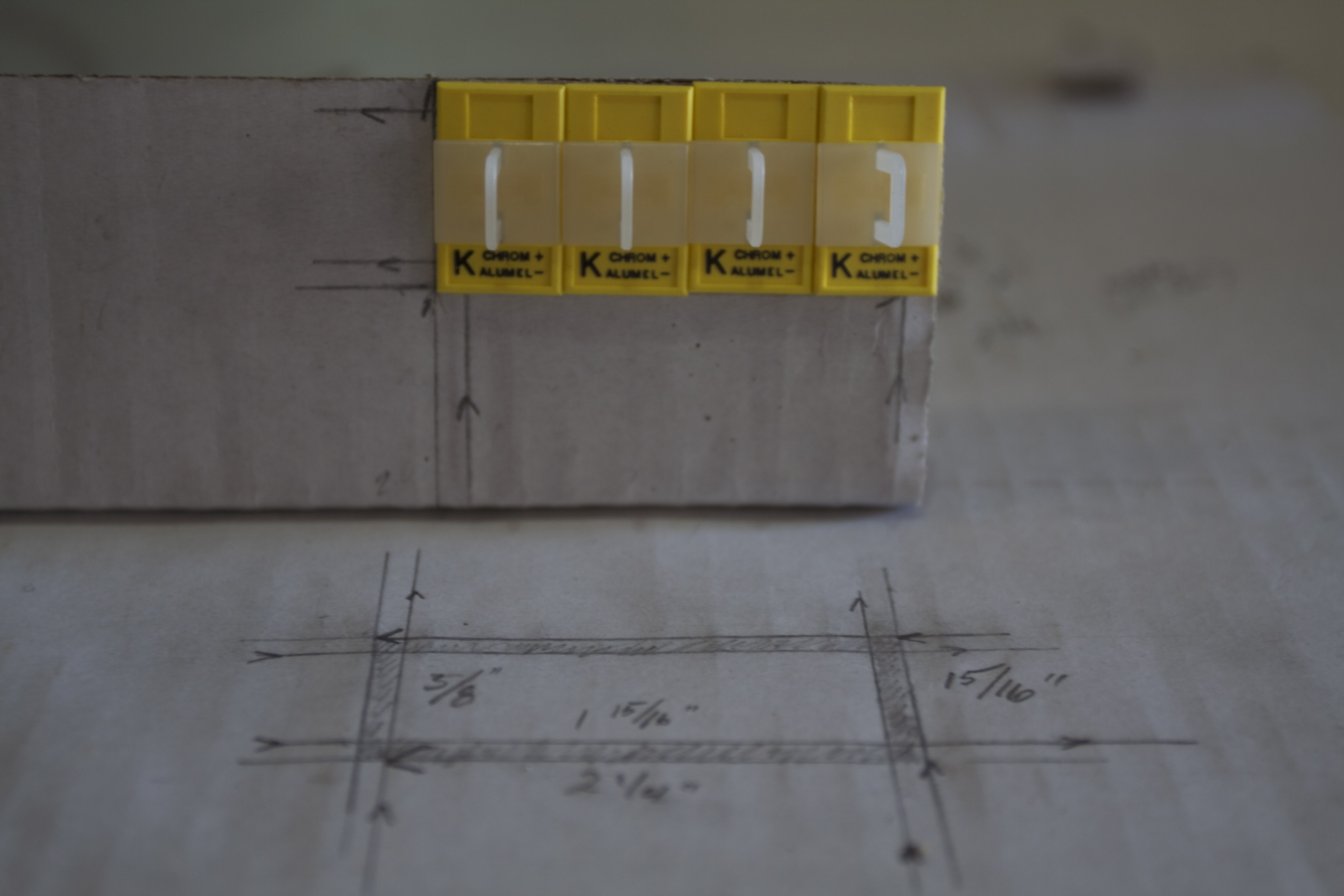
stripped leads terminationNextel Insulated Leads with Spade Lugs1, 3') - 4 mini panel jacks
- 2 retractable sensor cables RSCM-K-1-4-4 (Mini retractable cable, K-type, 1', and SMP-M(male) on both ends)
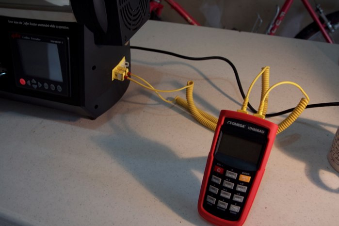
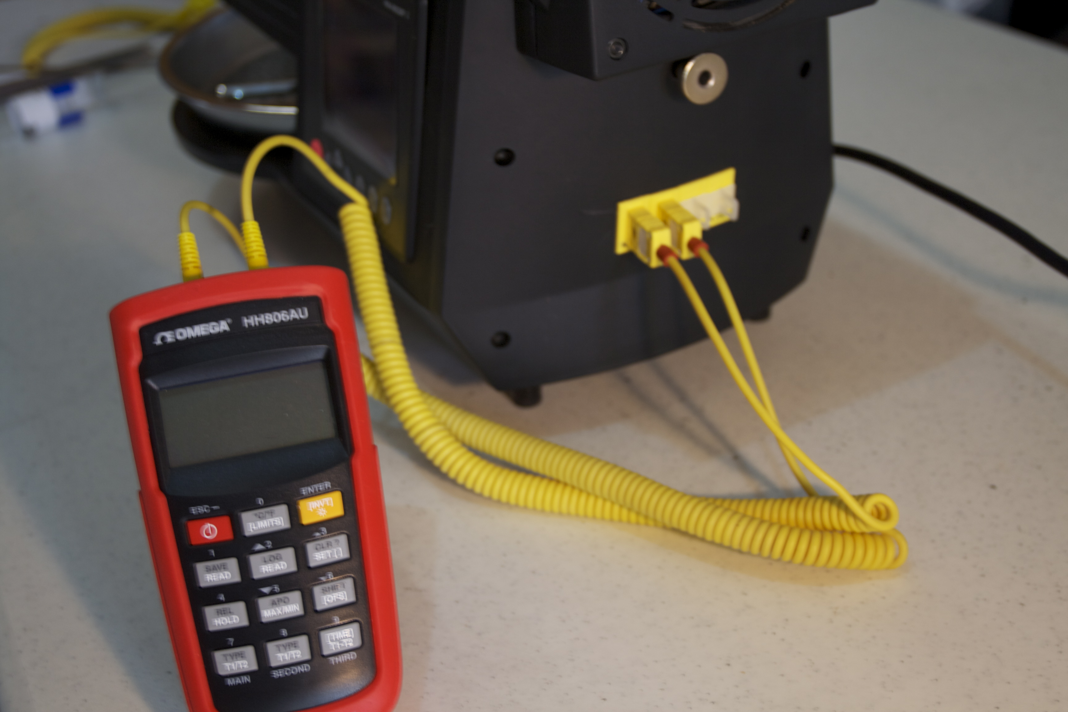
- Dual input thermometer/data logger HH806AU
- JB Weld Check the maximum rated temp. On the box mine says it's rated to 600°F. That's the minimum you want.
- 11/64" Cobalt drill bit
- Round file (optional, can be used to clean the holes after drilling, to help protect the probes)
- Flat file (optional, can be used to expand the square hole for the panel jacks)
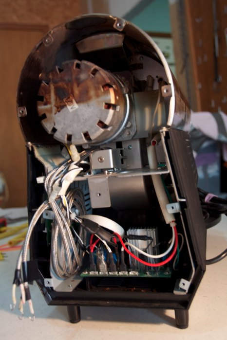
Step 1: Disassembly
Disassemble your roaster to the point where you have complete access to the back wall of the roaster. i.e. remove the front cover, the main fan, the rear cover, the stainless top cover, the roasting drum, and the internal drum. Also remove the main motor mounting bracket (leaving the motor on the bracket). I rested it on an empty soup can next to the roaster so that I didn’t have to unplug all the wires. Also remove the built-in temperature sensor to get it out of your way.
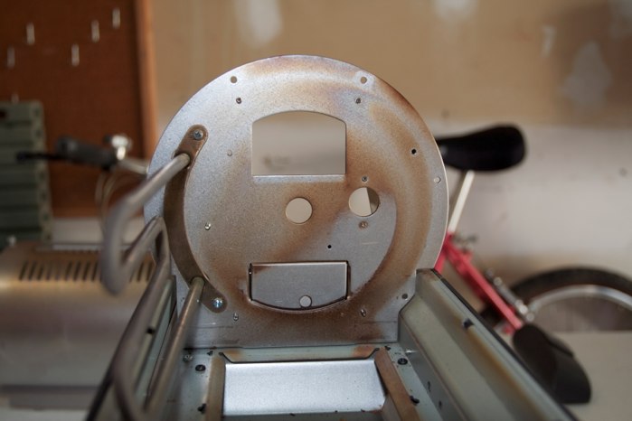
Step 2: Marking and drilling
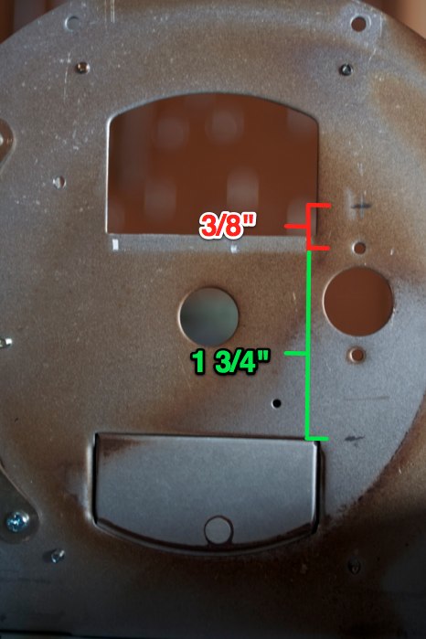
Mark the locations of your probes using the following measurements from the top screw hole of the built-in temperature sensor (see picture):
- For the environment temp (ET) probe, measure 3/8" above the top screw hole
- For the bean temp (BT) probe, measure 1 3/4" below the top screw hole
The BT mark will be even with the top of the bean ejection door.
Drill the marked holes using an 11/64” cobalt drill bit. Once you have both holes drilled, slowly clean the hole and enlarge it. Then try to pass a probe through the hole, enlarge it a bit more, and try again. Keep doing this very slowly until the hole is just big enough for the probe to pass through it.
Step 3: Installing the probes
Insert both probes and extend them 1” into the drum space. To secure the probes in place I used two hemostats and a pair of wood clamps; the hemostats clamped onto the probes and the wood clamps held the hemostats to the rear wall. This held the probes securely in place.
Use JB Weld high-heat epoxy (rated to at least 600°F) on the motor side of the wall to both seal the holes and secure the probes in place. Let the epoxy cure at room temperature for 6 hours (during which you can jump to the next step and install the panel jacks), then place a lamp directly over the epoxy to gently heat it overnight to finish the curing process.
Step 4: Installing the panel jacks
I installed four panel jacks in the back of my roaster; two will be immediately used (ET and BT probes) and two for future uses (maybe an MET probe and exhaust air temp probe).
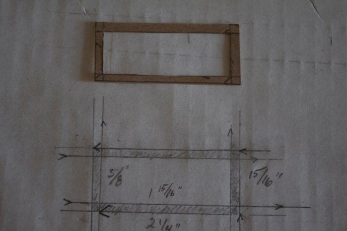
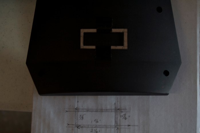
I started by building a cardboard mock-up with the center cut out to mount the jacks and verify all of my measurements. I then made a cardboard template that represented the space to be cut as well as the outer most edges of the jacks and I used that to determine the placement of the jacks in the rear cover 2” inches from the bottom of the panel and centered vertically.
I used a Dremel to cut the hole and then a flat file to slowly expand it to fit the jacks – test the fit, file if necessary, test again, repeat. Once the hole is the correct size, insert the jacks and attach the retaining clips to each and then set the cover and roaster aside until the epoxy from step #3 has fully cured (over night).
Step 5: Connecting probes to jacks and reassembly
Once the epoxy has cured overnight, you can reattach the motor assembly and built-in temperature sensor. Snake the new thermocouples under the motor assembly to the back of the roaster and then gently coil them into the space that houses the control panel. Leave 2 or three inches of the probes free to attach to the jacks.
If you bought stripped lead probes, gently curve the exposed leads of the probes into a “J” shape that can easily be hooked onto the mounting screws on the panel jacks. Attach the red-striped lead to the negative screw of the panel jack and the yellow-striped lead to the positive screw. Once you have both leads attached to the panel jacks, connect your data logger and test the whole setup. When you grab the business ends of the probes with your fingers, both readings on your data logger should increase. If either decreases, you need to reverse the positive and negative leads at that particular jack panel.
Once it all tests successfully, reassemble the roaster but leave the front panel off for now. Insert the roasting drum and gently turn it by hand one full rotation and see if anything touches the probe tips. I had to bend the BT probe towards the center axel and up a bit to avoid one of the drum fins. Once you’ve made sure nothing will come in contact with the probe tips, replace the front panel.
Step 6: Dry run to test everything
The last step is to do a dry run that takes your roaster up to full temperature (300-400°F) and cycles the main fan through all four settings. If anything comes in contact with the probe tips, adjust them and test again. If the fan doesn’t work, make sure the connection is firmly secure.
It’s normal for the ET to be higher than the BT because it is placed higher in the drum (heat rises).
1 After installing the thermocouples, I realized spade lugs would be the better termination.↩
Value 4 Value
If you found this content useful, please consider supporting my work. I charge no set fee or price for providing this. You can help keep information like this openly accessible by matching the value you received in the content; value 4 value.Ko-fi / Bitcoin Wallet: 32SW9kcAsJdZvQKBazhLUZBSD9YS8DDqe8